Schwarzkopf offers high-quality hair dye products known for their vibrant colors and gentle formulas. Trusted by professionals, their range includes ammonia-free options and conditioning properties for healthy-looking hair.
1.1. Overview of Schwarzkopf as a Trusted Brand
Schwarzkopf is a globally recognized and trusted brand in the hair care industry, with over 125 years of experience in delivering high-quality hair products. Known for its innovative solutions, Schwarzkopf has built a reputation for excellence, catering to diverse hair needs. Their hair dye products are celebrated for their rich, vibrant colors and long-lasting results, making them a favorite among both professionals and at-home users. The brand offers a wide range of formulas, including ammonia-free options, designed to minimize damage while providing intense color; Schwarzkopf’s commitment to quality, safety, and innovation has solidified its position as a leader in the hair dye market. With a focus on user-friendly products, Schwarzkopf ensures that achieving professional-grade results is accessible to everyone. Their formulations are infused with conditioning properties, promoting healthy and radiant hair. This dedication to excellence makes Schwarzkopf a go-to choice for those seeking reliable and effective hair dye solutions.
1.2. Popular Schwarzkopf Hair Dye Products
Schwarzkopf offers a wide range of popular hair dye products that cater to various hair types and color preferences. One of the most sought-after options is the LIVE Intense Colour line, known for its vibrant, long-lasting shades. The LIVE Intense Colour Deep Black 099 is particularly favored for its rich, permanent vegan formula, ideal for medium to dark hair. Another popular choice is the Schwarzkopf Colour Cream, which allows users to create custom shades by mixing with conditioner, offering flexibility and pastel options. These products are praised for their ease of use, conditioning properties, and ability to deliver professional-grade results at home. With a variety of shades and formulations, Schwarzkopf’s product range ensures there’s something for everyone, making it a top choice for hair color enthusiasts worldwide.
1.3. Benefits of Using Schwarzkopf Hair Dye
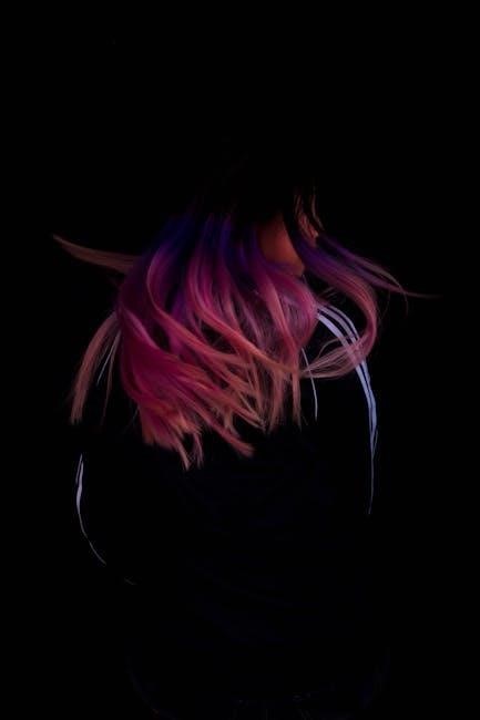
Using Schwarzkopf hair dye offers numerous benefits, making it a top choice for many. The products are known for their vibrant, long-lasting colors and gentle, conditioning formulas that care for your hair during the coloring process. Many Schwarzkopf dyes are ammonia-free, eliminating the strong, unpleasant smell often associated with hair coloring. Additionally, the range includes vegan-friendly options, catering to those with ethical or sensitivity concerns. The dyes are also praised for their ease of use, providing professional-grade results at home. With a wide range of shades, Schwarzkopf ensures that users can achieve their desired look, from natural tones to bold, statement colors. The inclusion of conditioning properties helps maintain hair health, leaving your locks looking vibrant and feeling soft. Overall, Schwarzkopf hair dye combines quality, versatility, and care, making it a preferred choice for hair color enthusiasts worldwide.
Preparing for Hair Dye Application
Proper preparation ensures the best results. Choose your shade, prepare your hair and skin, and conduct a patch test to avoid allergic reactions and achieve desired color accuracy.
2.1. Choosing the Right Shade for Your Hair

Selecting the perfect shade is crucial for achieving desired results. Consider your natural hair color, skin tone, and personal preferences. Schwarzkopf offers a wide range of shades, from natural tones to bold vibrants. For gray coverage, opt for formulas specifically designed to target and neutralize gray hairs effectively. If you’re aiming for a pastel look, you can mix the color cream with conditioner to create a softer hue. Always refer to the color chart provided with the product to ensure accuracy. Remember, the final color may vary based on your current hair condition and previous color treatments. Testing on a small strand before full application can help predict the outcome and guide your choice more precisely.
2.2. Preparing Your Hair and Skin
Proper preparation ensures a smooth and effective hair dyeing experience; Start by washing your hair 24-48 hours before application to remove dirt and oils, but avoid using conditioner, as it can create a barrier. Protect your skin by applying a thin layer of petroleum jelly or a barrier cream around your hairline, ears, and neck to prevent staining. Wear old clothing or an apron to safeguard against dye spills. If you have sensitive skin, consider using an ammonia-free formula or conducting a patch test first. Towel-dry your hair before applying the dye for better absorption. Ensure you have gloves ready to protect your hands during the process. These steps help create an ideal environment for the dye to adhere evenly and reduce the risk of irritation or uneven color distribution.
2.3. Conducting a Patch Test
A patch test is essential before applying Schwarzkopf hair dye to ensure safety and desired results. Mix a small amount of dye and developer, then apply it to a discreet area, like behind your ear or on a strand of hair. Wait 20-30 minutes to observe color development and check for any allergic reactions, such as redness or itching. This step is crucial, especially if you’re using the product for the first time or have sensitive skin. If irritation occurs, discontinue use. If no reaction appears, proceed with the full application. The patch test also helps you gauge the final color shade, ensuring it matches your expectations. Timing is key; leave the test dye on for the recommended duration to get accurate results. This simple step ensures a safe and satisfying hair dye experience.
Applying Schwarzkopf Hair Dye
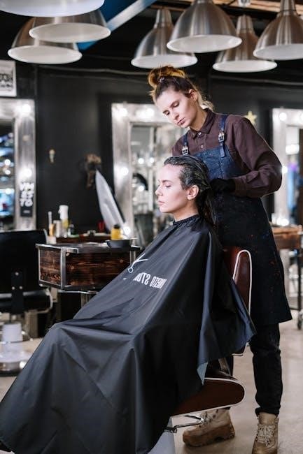
Apply Schwarzkopf hair dye evenly, starting at roots and working through ends. Use gloves, follow instructions, and process for recommended time to achieve vibrant, long-lasting color while caring for hair health.

3.1. Mixing the Hair Dye and Developer
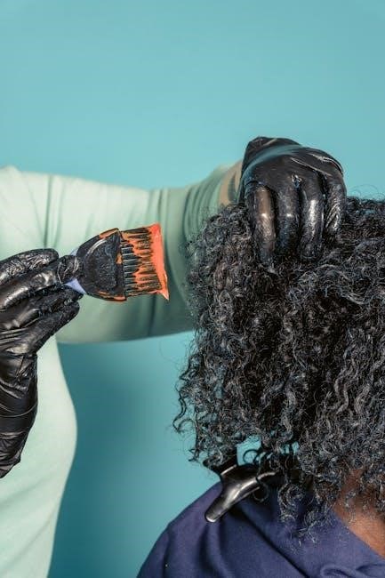
Mixing Schwarzkopf hair dye and developer is a critical step for achieving desired results. Always wear gloves and protective clothing. Combine the dye and developer in a well-ventilated area, using a plastic bowl and applicator brush. Follow the instructions for the correct ratio, typically 1 part dye to 1 or 2 parts developer, depending on the product. Stir thoroughly until the mixture is smooth and even. The developer strength varies based on the desired outcome, with options like 20-volume for depositing color and higher volumes for lifting. For ammonia-free formulas, the process is gentler but still effective. Once mixed, apply immediately to ensure optimal results. Proper mixing ensures vibrant, long-lasting color while maintaining hair health. Always follow the instructions precisely for best outcomes and to avoid damage.
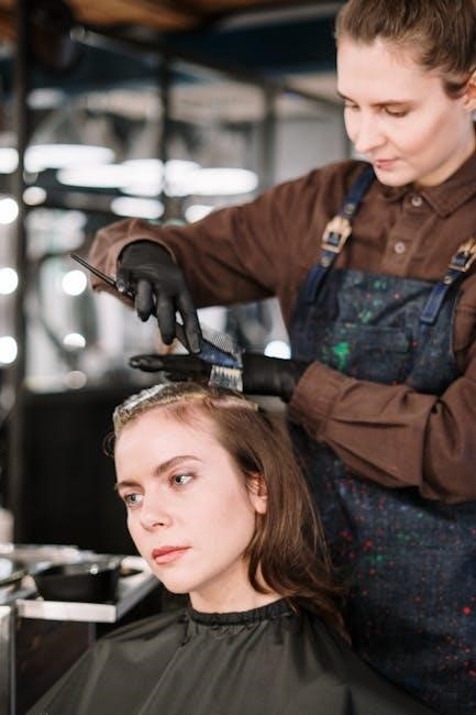
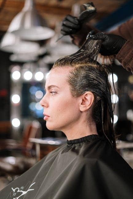
3.2. Applying the Dye to Your Hair
Applying Schwarzkopf hair dye requires precision for even coverage. Start by sectioning your hair, typically into four parts, to ensure thorough application. Use a tint brush to apply the dye mixture, beginning at the roots and working downward. For roots, focus on the regrowth area, while for lengths and ends, use a gentle, sweeping motion. Massage the scalp lightly to distribute the dye evenly. Avoid overlapping dye on previously colored hair to prevent damage. For ammonia-free formulas, the application is similar but gentler, reducing the risk of irritation. Leave the dye on for the recommended time, usually 20-35 minutes, before rinsing. Always rinse with warm water until the water runs clear, then condition to lock in color and moisture. Proper application ensures vibrant, professional-looking results at home.
3.3. Timing and Processing
Timing is crucial when using Schwarzkopf hair dye to achieve the desired results. Most Schwarzkopf products require processing time between 20 to 35 minutes, depending on the product and your hair type. For vibrant, long-lasting color, follow the instructions carefully. After applying the dye, leave it on for the recommended duration to ensure proper color development. Avoid processing for too long, as this can damage your hair or cause over-toning. For sensitive scalps, some formulas are designed to work gently within a shorter time frame. Once the processing time is up, rinse thoroughly with warm water until the water runs clear. This step is essential for removing excess dye and preventing residue buildup. Proper timing and rinsing ensure a professional finish and maintain the health of your hair. Always check the specific product instructions for precise guidance, as processing times may vary slightly between different Schwarzkopf ranges.

Aftercare and Maintenance
Proper aftercare ensures long-lasting color vibrancy and hair health. Use color-protecting shampoos, avoid heat styling, and moisturize regularly; Touch-ups every 4-6 weeks maintain roots and color intensity effectively.
4.1. Rinsing and Conditioning
Rinsing and conditioning are crucial steps after applying Schwarzkopf hair dye. Start by rinsing your hair thoroughly with warm water until the water runs clear, ensuring all dye residue is removed. Use the conditioner provided in the Schwarzkopf kit or a color-protecting conditioner to lock in the color and moisture. Leave the conditioner on for 1-2 minutes before rinsing to maximize its benefits. Avoid using hot water, as it can strip the color from your hair. Gently towel-dry your hair and avoid heat styling for at least 24 hours to allow the color to set fully. Proper rinsing and conditioning help maintain color vibrancy and prevent dryness, ensuring your hair looks healthy and vibrant for weeks to come.
4.2. Touching Up Roots and Regrowth
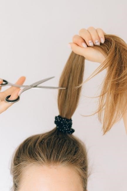
Touching up roots and regrowth is essential to maintain a consistent hair color. Use the same Schwarzkopf dye shade to ensure a seamless match. Apply the dye only to the roots or regrowth areas, avoiding overlap with previously colored hair. Follow the same mixing and timing instructions as the initial application. For smaller touch-ups, mix a quarter of the dye and developer. Processing time remains the same, typically 20-35 minutes. After rinsing, apply conditioner to hydrate and blend the color. Regular touch-ups every 4-6 weeks will keep your hair looking vibrant and even. Always perform a patch test before touching up, especially if you’ve changed products or have sensitive skin. Properly maintaining roots ensures a polished look and prevents harsh color lines. For best results, use Schwarzkopf’s aftercare products to preserve color and moisture.
4.3. Maintaining Color Vibrancy
To keep your Schwarzkopf hair dye looking fresh and vibrant, use color-protecting shampoos and conditioners. These products are formulated to lock in pigments and prevent fading. Avoid using hot water, as it can strip color from your hair. Instead, rinse with warm or cool water to preserve vibrancy. Regularly using a color-depositing treatment or mask can enhance and maintain the intensity of your shade. For extra care, apply a color-refreshing spray to revive tones between washes. Minimize the use of heat styling tools, as they can cause color to fade faster. When you do use heat, apply a heat protectant to shield your hair. For long-lasting results, touch up roots and regrowth every 4-6 weeks. By following these steps, you can enjoy rich, vibrant hair color for weeks after your initial application.